Analysis and estimation of dissipated power of power amplifier
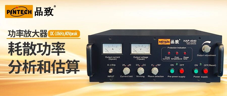
Analysis and estimation of dissipated power in power amplifiers. In the application of power amplifier driven loads, dissipated power evaluation is the key to ensuring that the load operates in a safe zone under any operating conditions. The discussion here is about linear power amplifiers, whose theoretical limit conversion efficiency for outputting sine waves is only 70%.
The analysis and estimation of dissipated power have the following steps:
Load demand analysis: Clarify the voltage, current amplitude, signal waveform, and operating frequency required for load operation.
Amplifier compatibility verification: Confirm that the selected amplifier meets the load requirements in terms of voltage, current, frequency, and operating mode (constant voltage/constant current/constant power).
Deduction and estimation of dissipated power.
Application safety assessment: Compare the dissipated power of the load in practical applications with the rated dissipation capacity of the amplifier to ensure that it operates in a safe zone.
Among them, the first and second steps are directly determined by the load specifications, while the estimation of dissipated power in the third step needs to be derived through circuit theory and amplifier parameters.
Estimation method of dissipated power: taking HAP4040 as an example
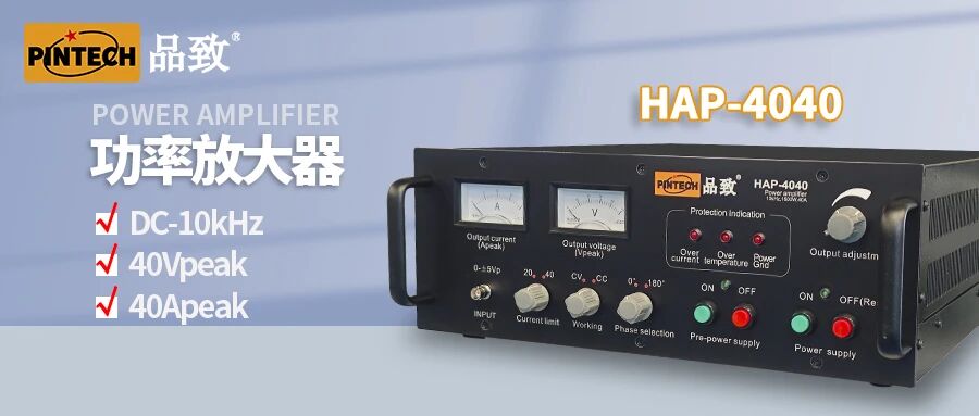
Given the key parameters of amplifier HAP4040:
Peak output voltage: 40 Vp
Peak output current: 40 Ap
Working bandwidth: DC -10 kHz
The estimation process is as follows:
Calculate the maximum output power and DC power supply demand
The maximum undistorted output power of an amplifier is usually calculated based on a sine wave signal. The maximum RMS output power is: (40Vp ≈ 28.3Vrms, 40Ap ≈ 28.3Arms) P_rms=28.3 * 28.3 ≈ 800W
The mainstream type of power amplifier on the market is Class AB amplifier, assuming a conversion efficiency of 70%.
According to the formula: dissipated power=input power - output power, and assuming a conversion efficiency of 70% and the remaining 30% as heat loss, the amplifier dissipated power is calculated as Pd=(800/70%) * 30% ≈ 343W
Practical application scenario verification
Given actual load conditions: operating frequency 1kHz, voltage ≤ 20Vrms, current ≤ 13.8Vrms.
The calculation process assumes that the power supply voltage of the amplifier is 40V (assuming that the power supply voltage=output voltage is beneficial for estimating the minimum range of dissipated power and ensuring safe use):
Assuming a load of 5Vrms/13Arms:
Pd=(40-5)*13=455W>343W
Under this operating condition, if the dissipated power is greater than the estimated value (343W), it is not recommended to use it. If it is necessary to use it, it is necessary to consider connecting a high-power resistor in series with the load (transferring dissipated power to this resistor) or pulse train mode.
Assuming a load of 20Vrms/13Arms:
Pd=(40-20)*13=260W<343W
Under this operating condition, the dissipated power is less than the estimated value (343W), and the amplifier's heat dissipation capability is fully met. Therefore, the 20Vrms/13Arms load parameter can be safely used.
Based on analysis, dissipated power is directly related to the reliability and stable operation of the amplifier, and load conditions can be easily evaluated using the above methods.