
Principle of Capacitor Transient Discharge: Mechanism of High Current Generation
In the paper “Analysis of Capacitor Discharge Transient Currents Using Flexible Probes,” we delved into the process of measuring capacitor discharge transient currents. But how does a capacitor generate such high currents? The following section will focus on explaining the mechanism behind this high-current generation.
The physical nature of capacitive energy storage determines its potential for energy releaseThe capacitor's ability to store electrical energy is directly related to its physical structure:
The inevitability of charge accumulation
When an external power source charges a capacitor, equal and opposite charges (±Q) accumulate on the plates separated by the dielectric. This charge separation phenomenon is essentially the result of the dielectric polarizing in response to the electric field. Its energy storage density is jointly determined by the capacitance value C and the applied voltage V, as expressed by the following formula:
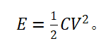
The essence of high-voltage charging lies in establishing a strong electric field, which lays the energy foundation for subsequent high-current discharge.
The driving effect of voltage
During discharge, the potential difference between electrodes creates a non-equilibrium electric field system. According to the principle of electrostatic force, this electric field force inevitably drives charges to migrate directionally through an external circuit to restore electrical neutrality. The initial amplitude of the voltage directly determines the driving force intensity for charge migration, which is the fundamental constraint on the peak value of the pulse current.
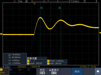
Figure 1: Transient Peak Current Waveform of Capacitor Discharge
Sufficient and Necessary Conditions for Generating High CurrentThe root cause of high current: low-impedance path
The total loop resistance R is the core parameter governing the current magnitude. CBB capacitors feature low equivalent series resistance (ESR), which minimizes energy loss and impedance. According to Ohm's Law.

When wire resistance, contact resistance, and other factors are reduced to the milliohm level, currents in the ten-thousand-ampere range become feasible.
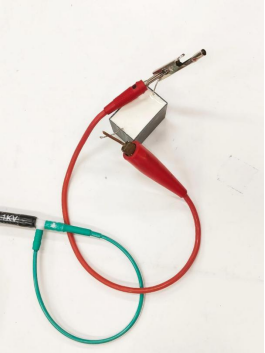
Figure 2 Capacitor Connection Diagram
Figure 2 shows the capacitor connection diagram. The connecting wire is attached to one side of the capacitor, while the other side connects to a copper rod touching the capacitor. The clip-around coil is looped around the connecting wire, with the red capacitor connecting wire serving as a low-impedance path.
Physical Limits on Energy Release Rates
The pulse power requirement is P ≥ E/Δt (where Δt is the pulse width). As shown in the following formula:

It is evident that low-resistance design not only amplifies current amplitude but also ensures efficient energy release in the form of electromagnetic energy by reducing the proportion of thermal energy conversion. A typical example is the xenon discharge tube, whose plasma channel resistance can be as low as 0.001Ω, enabling microsecond-level currents of thousands of amperes.
ConclusionThe high-frequency, high-current characteristics of capacitor discharge pulses fundamentally stem from the intrinsic properties of the energy storage component (which follows the energy relationship E = 1/2CV?). Its current amplitude is jointly determined by the initial voltage V0 and the total resistance R of the circuit, Ohmic loss has become the key factor limiting energy conversion efficiency. For precise measurement of such transient high currents, a wide dynamic range current probe is employed to prevent signal saturation. PINTECH DK-0700 Flexible Current Probe, featuring a non-invasive design, high current tolerance, and wide bandwidth characteristics, is recommended for applications such as capacitive discharge pulse measurement.