
The impact of impedance mismatch in output terminals

In testing, the matching degree between the output impedance of the actual signal source and the terminal impedance directly determines the waveform quality of the reference signal, the authenticity of the test data, and even affects the safety of the instrument and the tested part.
50 Ω and 1M Ω are the two most commonly used terminal impedances in electronic measurement: 50 Ω is the standard impedance for RF/high-frequency testing (matching with RF equipment such as signal sources and spectrometers); 1M Ω is a typical impedance for high impedance testing (suitable for high impedance requirements of equipment such as oscilloscopes, power amplifiers, and low-frequency distortion meters). Incorrect impedance matching can cause vastly different waveform distortions, test failures, and even equipment self excitation, device damage, and other issues. The following analysis will be based on specific testing scenarios.
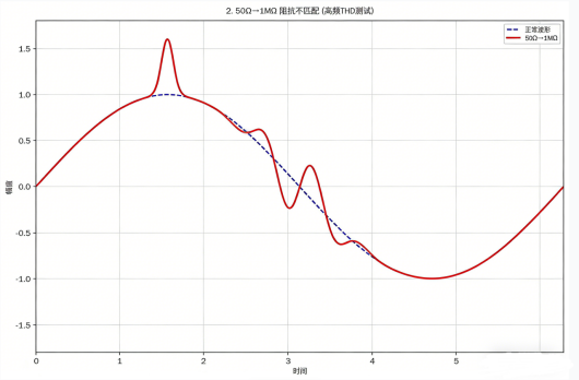
1. The testing requirement requires a 50 Ω impedance matching terminal, but a 1M Ω terminal impedance is selected
In high-frequency testing, when the specification requires the terminal to be set to 50 Ω for impedance matching, it is mistakenly set to 1M Ω. However, the impedance matching of the source output is optimized for a 50 Ω load. After connecting the extension line, the distributed capacitance of the extension line is "amplified" under high impedance, equivalent to connecting to a capacitive load. It manifests as severe distortion of the output waveform, with peaks, overshoot, or irregular clutter appearing in the standard sine wave; The deterioration of spectral characteristics, unstable fundamental amplitude, and chaotic harmonics can lead to the failure of test data and may also cause oscillation and equipment burnout risks.
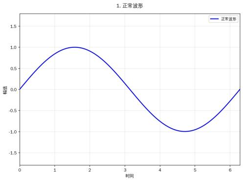
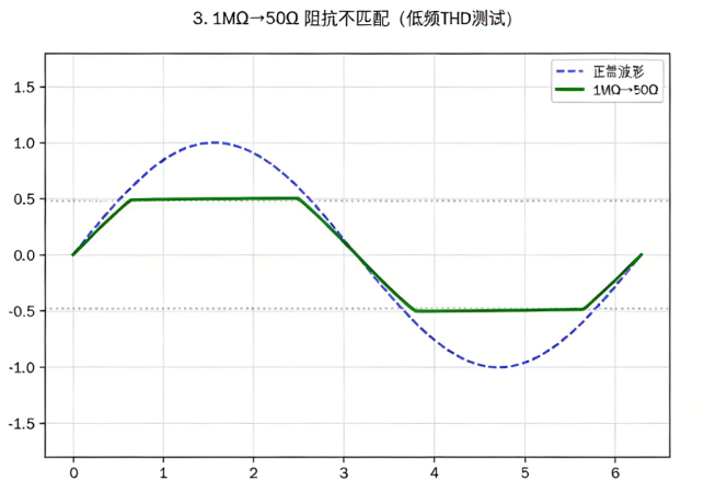
2. The testing requirement requires a 1M Ω impedance matching terminal, but a 50 Ω terminal impedance is selected
When using power amplifiers or passive probes for testing, the specification requires a matching terminal impedance of 1M Ω, but it is mistakenly set to 50 Ω. At this time, the source terminal is in voltage driven mode, and the driving capability is only suitable for high impedance loads. When the terminal is matched with an impedance of 50 Ω, it is equivalent to heavy load. It manifests as output voltage division, waveform top and bottom clipping distortion, and voltage amplitude drop due to insufficient signal source driving caused by low impedance loads requiring larger driving current; The amplitude attenuation is severe and fluctuates irregularly with frequency, which can also cause problems such as insufficient driving and distortion misjudgment.
In summary, impedance matching of instrument output terminals is a fundamental prerequisite for testing. Incorrect matching not only renders the test data completely invalid and unable to reflect the true performance of the tested component, but also poses varying degrees of equipment damage risk.