
How to Reduce Measurement Errors Through Oscilloscope Settings
Measurement error refers to the discrepancy between the measured result and the true value of the quantity being measured. The greater the measurement error, the lower the reliability of the measurement result. This article will explore how errors arise from improper oscilloscope settings, their typical manifestations, and how to reduce measurement errors through proper oscilloscope configuration.
Measurement Error of an Oscilloscope
Oscilloscope measurement errors may be caused by factors such as hardware limitations, improper settings, environmental interference, and human operation. Below are the causes of oscilloscope errors and their typical manifestations:
Error Type | Causes | Typical Manifestations |
Incorrect vertical scale | Range too large (signal amplitude too small, significant quantization error) or too small (signal clipping) | Amplitude measurement error or waveform clipping |
Inappropriate horizontal range | Time base range is too small or too large | The waveform is stretched and difficult to recognize. The waveform is compressed, making it impossible to observe details. |
Trigger configuration error | Improper selection of trigger level/edge causes unstable waveforms. | Waveform jitter or synchronization failure |
Coupling Mode Error | AC coupling filters out the DC component, while DC coupling introduces offset. | DC level loss or baseline drift |
Incorrect probe attenuation ratio setting | The oscilloscope channel attenuation ratio doesn't match the actual attenuation ratio of the probe (e.g., 10:1). | Amplitude display error (e.g., 10-fold deviation) |
Limitations of Measurement Methods | Automatic measurement parameters (such as Vpp) are affected by noise, or the cursor's manual measurement position is inaccurate. | The statistical results of amplitude parameters show significant fluctuations. |
By systematically analyzing the sources and manifestations of measurement errors, measurement protocols can be optimized to enhance measurement accuracy.
Optimizing Basic Oscilloscope Settings
Vertical System (Voltage):
Select the appropriate range: Signal amplitude should occupy 60% to 80% of the screen (to avoid quantization errors from too small signals or clipping from too large signals).
Disable “Bandwidth Limiting” (unless needed to suppress high-frequency noise).
Horizontal System (Time Base):
The time base setting should display 1 to 2 complete signal cycles (e.g., use 500 ns/div for a 1 MHz signal).
Enable “High Resolution Mode” (reduces noise at the expense of bandwidth).
Trigger Settings:
Trigger Mode Selection:
Edge Triggering: Suitable for periodic signals (e.g., square waves, sine waves).
Pulse Width Triggering: Captures abnormal pulses.
Trigger Level Adjustment: Sets the trigger level at 50% of the signal amplitude (prevent false triggering).
Operational Case: Magnitude of Background Noise at Different Attenuation Ratios
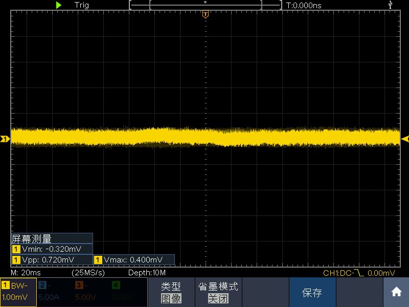
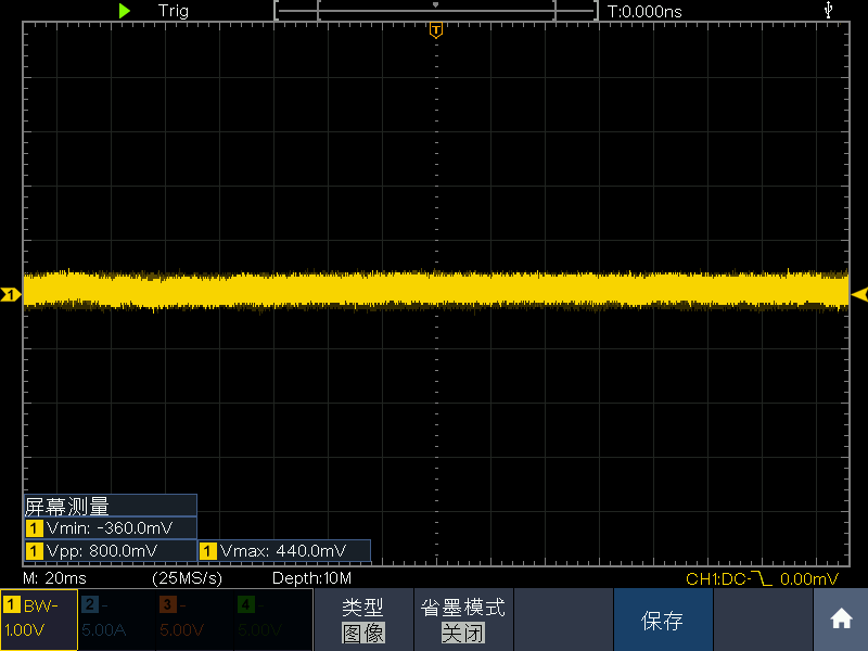
Figure 1 shows Channel 1 of the oscilloscope with no probe connected, attenuation ratio set to 1X, and floating ground. With the vertical range set to 1.00 mV/div, the measured background noise is 0.72 mV Vpp.
Figure 2 shows Channel 1 of the oscilloscope with no probe attached, attenuation ratio set to 1000X, and no signal applied. With the vertical range set to 1.00V/div, the measured baseline noise is 800mV Vpp.
This amplified baseline noise results from the noise superposition effect of the attenuator: The oscilloscope's baseline noise primarily originates from the attenuator and preamplifier. At a 1000:1 attenuation ratio, the signal is significantly attenuated. The oscilloscope then compensates by amplifying the signal to restore its amplitude. This process synchronously amplifies the attenuator's inherent noise. Under identical conditions, selecting different probe attenuation ratios will cause significant variations in the baseline noise. This baseline noise affects the system measurement results, representing an unavoidable measurement error introduced by the setup.
How does this knowledge help our measurements? Suppose I have a probe with attenuation ratios of 100:1 and 1000:1 attenuation ratio. If the signal level range is unknown, prioritize the higher attenuation ratio (1000:1) for initial measurement. Should the results indicate the signal falls within the 100:1 range, switch to the 100:1 setting to minimize background noise and enhance measurement accuracy.
Conclusion: Within the measurement range, selecting a smaller attenuation ratio will also reduce background noise, thereby mitigating measurement errors to a certain extent.
Operational Example: Magnitude of Background Noise at Different Ranges
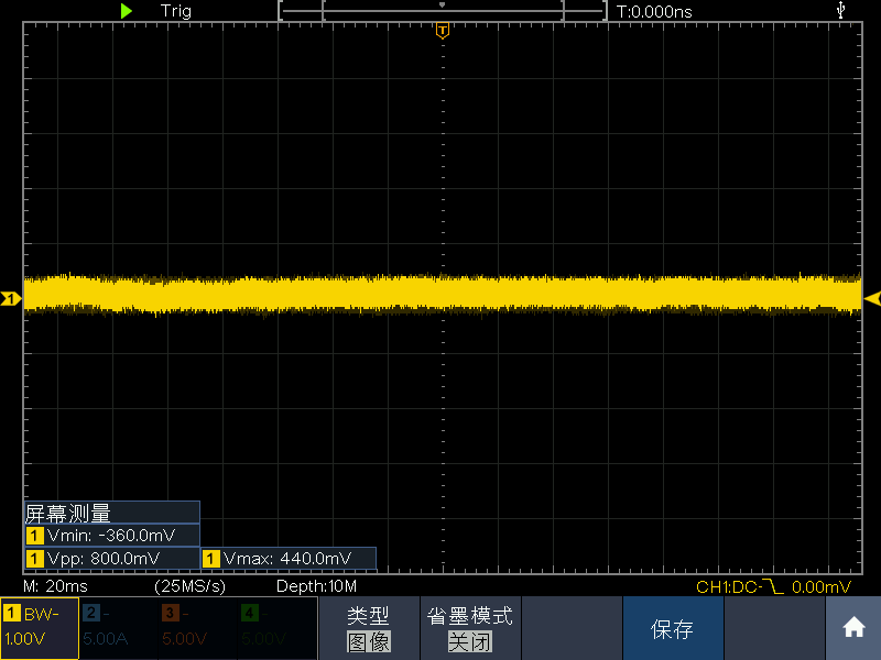
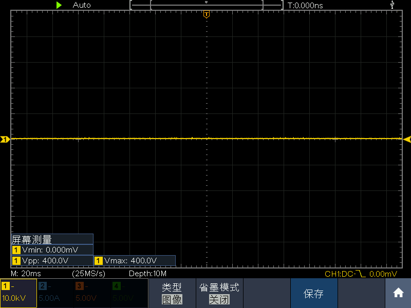
Figure 3 shows the oscilloscope Channel 1 with no probe attached, attenuation ratio set to 1X, and floating. With the vertical range set to 1V/div, the measured background noise is 800mV Vpp.
Figure 4 shows the oscilloscope's Channel 1 with no probe connected, attenuation set to 1000X, and the vertical range set to 10.0kV/div. The measured background noise is 400V Vpp. The primary cause of these results is vertical resolution limitation: the oscilloscope's vertical resolution is determined by the ADC's bit depth (e.g., 8-bit, 12-bit). If the range is too large, the dynamic range of the signal occupies fewer quantization levels of the ADC, leading to loss of amplitude detail.
As shown in Figure 4: An 8-bit ADC divides the range into 256 levels. A single division corresponds to 10kV, with a total range of 100kV. each level corresponds to 100kV/256≈390V, practically 400V. With background noise at 800mV in the 1000X range, occupying one level, the measurement results may display Vmax as 0V or 400V; similarly, Vmin could show as 0V or -400V due to noise and resolution limitations.
Due to resolution limitations, a larger vertical range causes the ADC to measure and interpret higher voltages, directly impacting measurement accuracy.
Conclusion: The ADC (analog-to-digital converter) resolution of an oscilloscope is limited. Using a high range to measure small signals introduces quantization error, resulting in inaccurate amplitude measurements.
Summary
Inappropriate attenuation ratio selection or incorrect vertical range selection may introduce quantization errors, leading to elevated measurement errors. Proper oscilloscope settings can minimize measurement errors.